ANSYS-Driven Flow Straightener
Project Summary
- For senior capstone, a flow straightener was needed to disperse a jet of fluid entering a tank and ensure a near-constant parabolic fluid velocity profile in the rest of the tank.
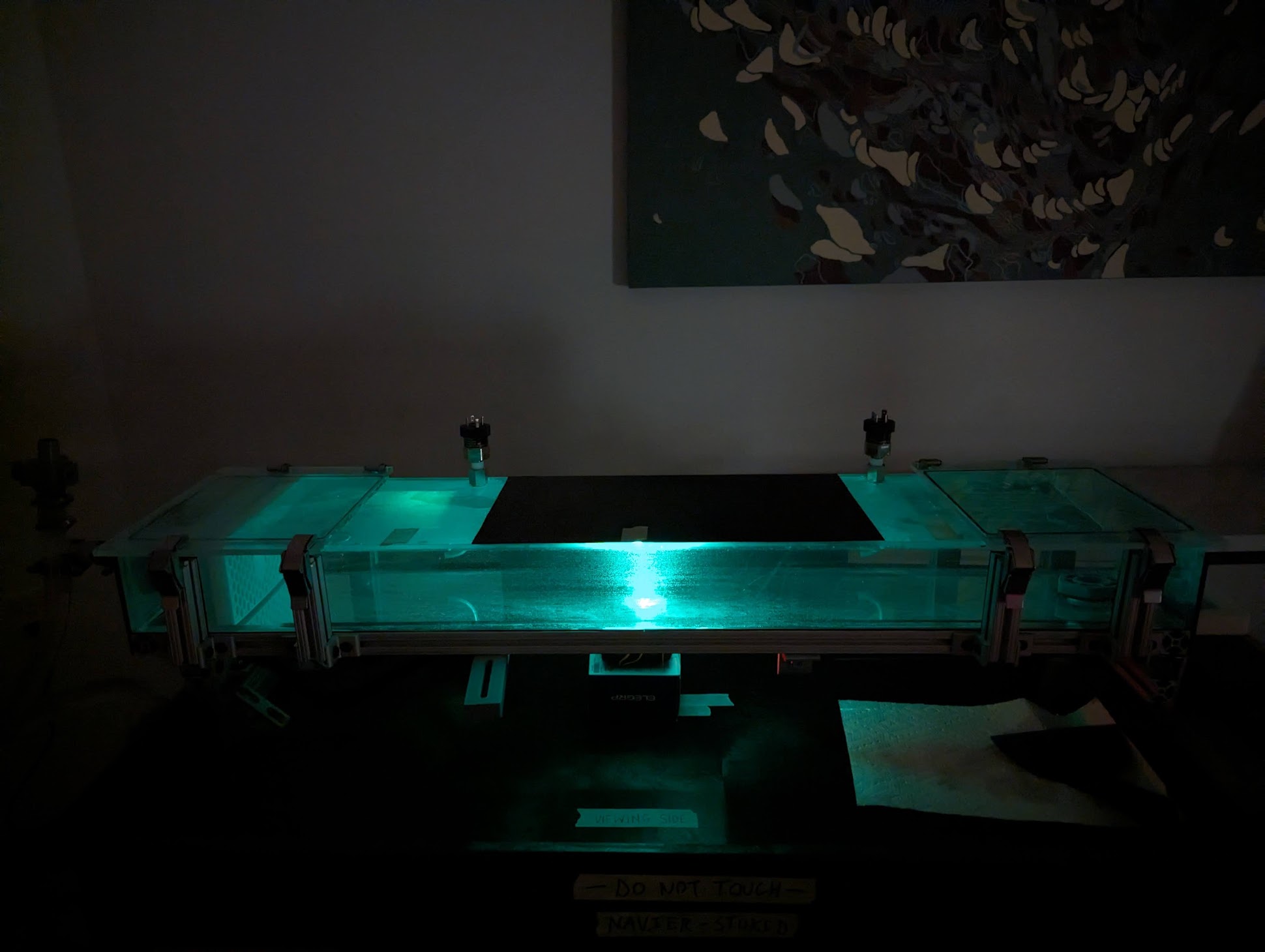
Final capstone prototype visualizing Navier-Stokes.
Design Steps
- A simplified SOLIDWORKS model representing the system fluid volume was built containing one iteration of the flow straightener.
- The model was imported into ANSYS Fluent R2 and meshed with the watertight geometry workflow and solved with a laminar model and mass flow input/output boundary conditions.
- The resulting velocity data was analyzed in MATLAB and used to adjust the geometry of the flow straightener.
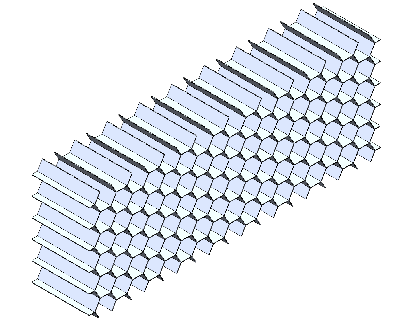
Original flow straightener.
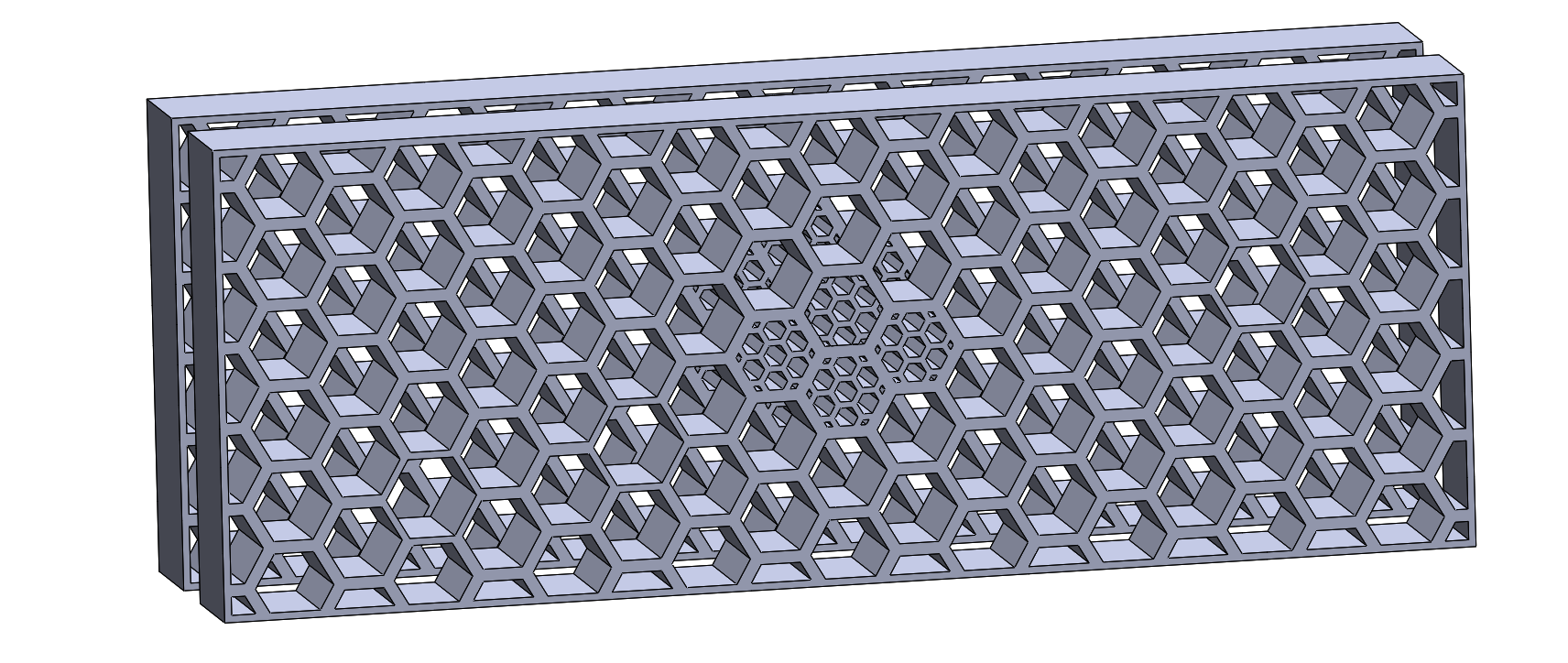
Final flow straightener.
Challenges
- The large size of the overall fluid volume and the small details of the honeycomb flow straightener resulted in meshes with over 1 million cells. To speed up processing times and reduce unnecessarily dense meshes, bodies of influence were used to concentrate mesh detail in critical regions.
- There was a negative correlation between a high maximum velocity and a well-dispersed, parabolic velocity profile. To maintain a reasonably fast velocity while also minimizing the jet effects, a combination of small honeycombs, multiple straighteners, and obstacles in front of the jet entrance were used.
Results
- The final iteration of the flow straightener resulted in a fairly parabolic velocity profile along a length of around 0.5 m of the tank at a maximum velocity of around 0.87 in/s, close to the expected speed of the fluid. This ensured that the project’s goal of visualizing a parabolic velocity profile using particle image velocimetry was plausible.
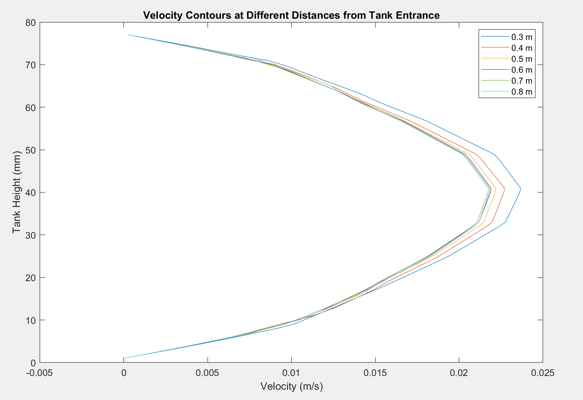
ANSYS Fluent output graphed via MATLAB describing the parabolic velocity profile at each distance from the pipe entrance.
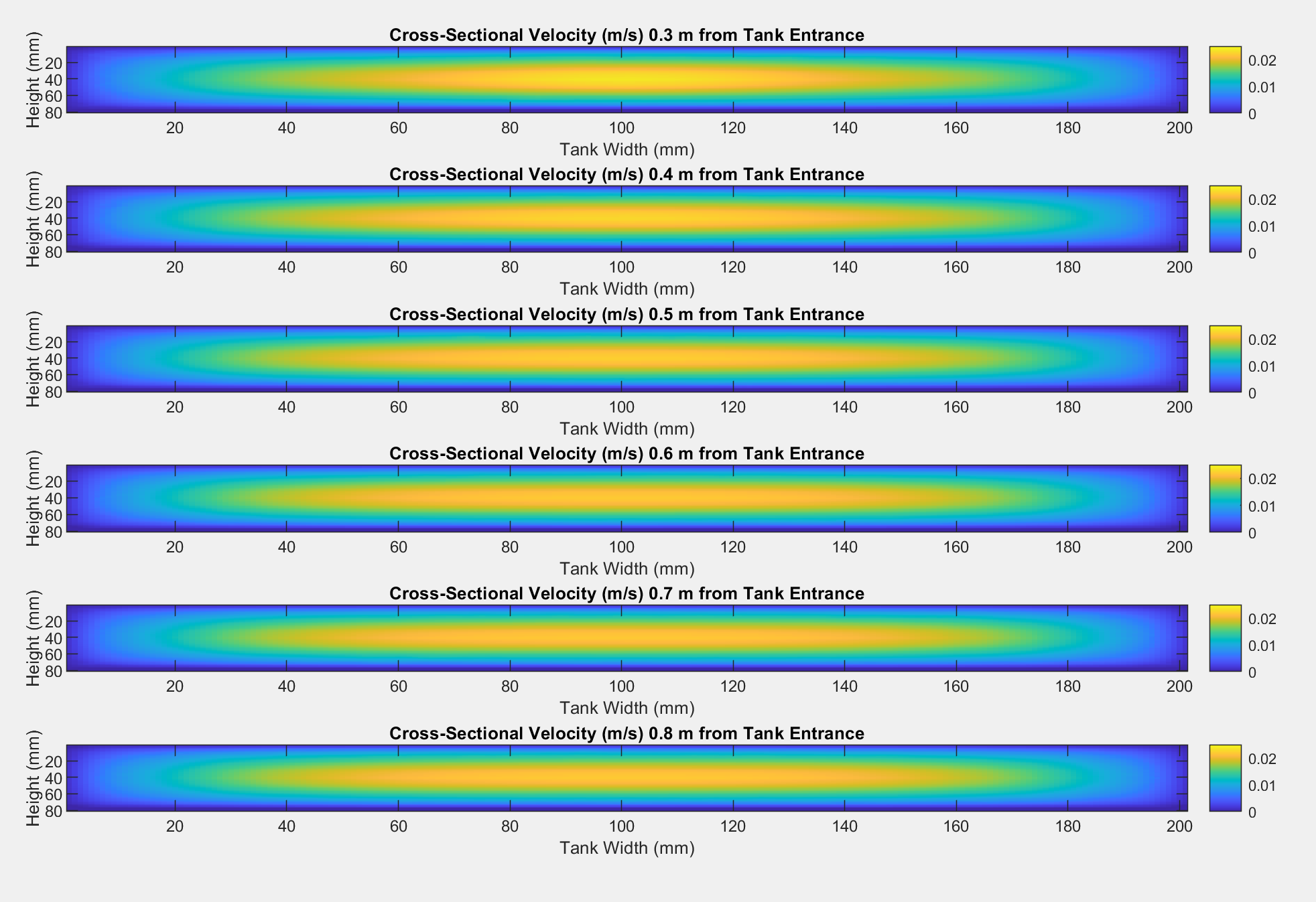
ANSYS Fluent output graphed via MATLAB describing the cross-sectional velocity profile at each distance from the pipe entrance.
- Once the final prototype was built, these theoretical results aligned with our experimental results using particle image velocimetry (PIV) to track the fluid velocity in the tank.
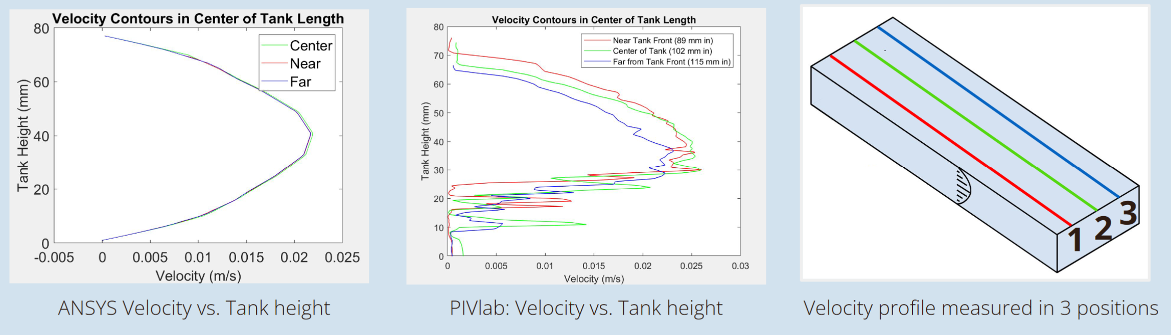
Theoretical ANSYS and experimental PIV results are aligned.
Skills Developed
- Generating and interpreting CFD analysis results to make design enhancements
- Synthesizing the results of previous iterations into an improvement